InterProcess Sp. z o.o. | Solutions for industry

The DSL G family
Three sizes, one operating principle
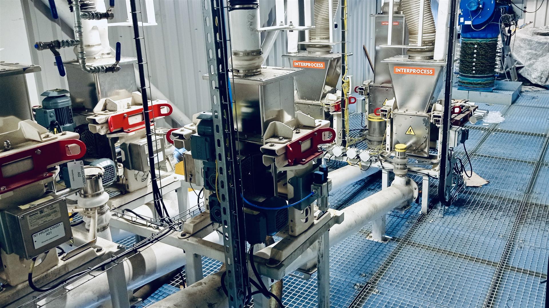
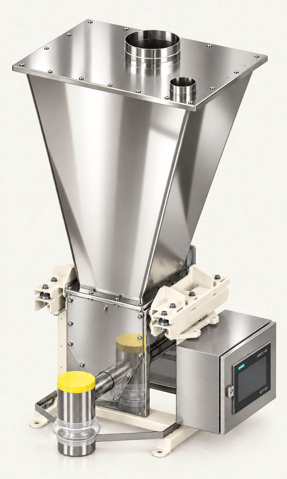
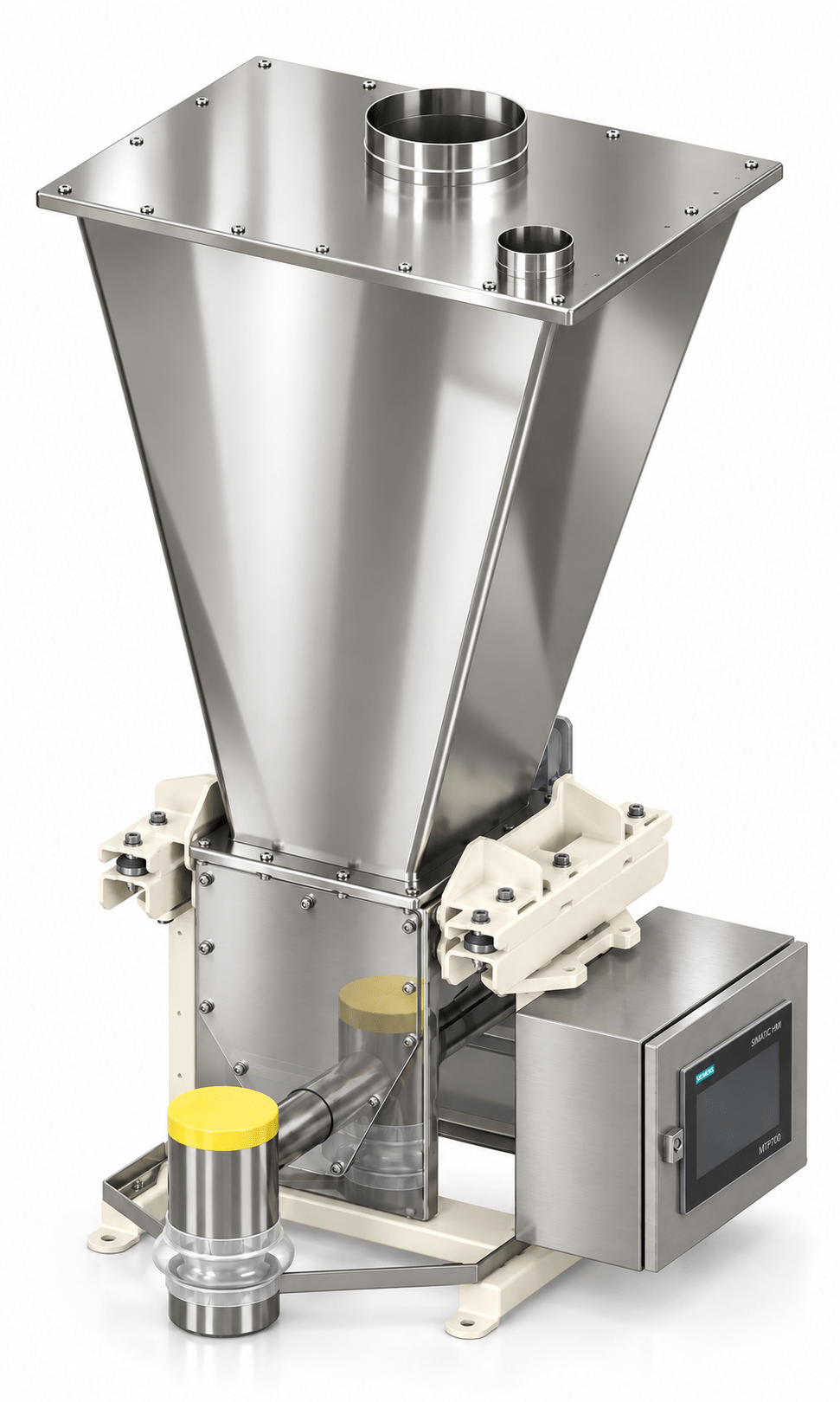
Every DSL G feeder consists of a hopper, a chamber holding the feeding element, a horizontal agitator and a drive. The whole assembly rests on load cells: the controller measures the loss in weight, derives the actual mass flow and uses a PID loop to correct screw speed. A change in bulk density does not affect the result, because what is being controlled is mass, not volume.
Throughputs are given by volume. Mass flow = throughput × bulk density of the material, for example 200 l/h × 0.55 kg/l ≈ 110 kg/h. The minimum applies to the smallest full-flight screw at 10 rpm, the maximum to the largest spiral at 200–250 rpm.
DSL35 G screw feeder
Micro-ingredients at laboratory accuracy
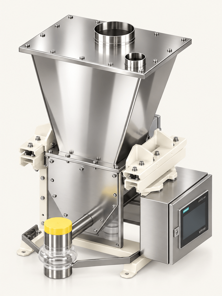
The smallest model in the family, intended for low rates and expensive raw materials. Screws of ø18–35 mm deliver an even stream at rates as low as a kilogram an hour, and the steep-walled 30–65 l hopper enforces uniform emptying. Its low height allows the feeder to sit directly above a recipe scale, a mixer or an extruder inlet.
Configuration
A chamber with one horizontal agitator, a 30, 40 or 65 l hopper with a lid and filling spigot, and an outlet with a discharge tube. A weighing frame on two C3 load cells. Optionally a weighing controller with an HMI panel in a stainless steel enclosure, an EHEDG hygienic version and an ATEX build.
DSL35 G specifications
- Throughput1 – 450 l/h
- Feeding elementscrew or spiral ø18 – ø35 mm
- Hopper30 · 40 · 65 l
- Typical materialsmicro-ingredients, colourants, flavourings, APIs
DSL75 G screw feeder
The standard for production lines
The model specified most often for recipe ingredients on continuous and batch lines. Feeding elements of ø35–74 mm handle both fine cohesive powders and granules, while 100–300 l hoppers let the refill frequency be matched to the line’s output. It is the typical unit in multi-ingredient stations, where several DSL75 G feeders work in parallel into a common scale or mixer.
Configuration
A chamber with one or two horizontal agitators, a 100, 200 or 300 l hopper and a weighing frame on three C3 load cells. Filling by hand, from a big bag or through a rotary valve, with automatic refill on a minimum level signal. Optionally an additional vertical agitator, an EHEDG hygienic version and an ATEX build.
DSL75 G specifications
- Throughput7 – 5,000 l/h
- Feeding elementscrew or spiral ø35 – ø74 mm
- Hopper100 · 200 · 300 l
- Typical materialsrecipe ingredients, premixes, fillers
DSL150 G screw feeder
Industrial throughput
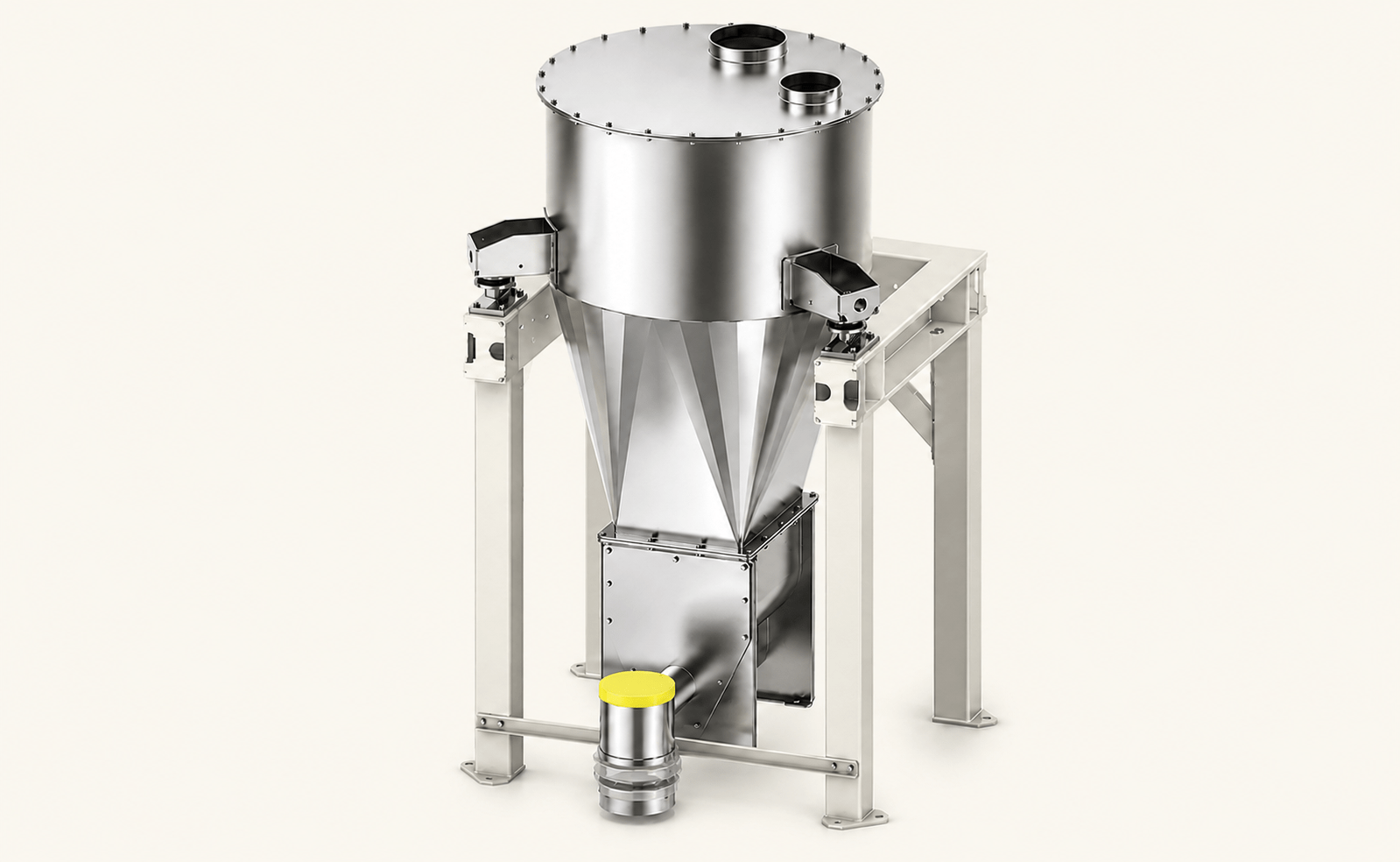
The largest model, for major raw materials and high mass flows. Feeding elements of ø74–150 mm, cylindrical hoppers from 400 to 2,400 l and a weighing frame prepared for filling from big bags, through a rotary valve or by pneumatic conveying.
Configuration
A cylindrical hopper of ø850 mm (400 or 600 l) or ø1200 mm (1,200, 1,800 or 2,400 l), a chamber with two horizontal agitators and a weighing frame on three C3 load cells sized for the mass of the full hopper. Automatic filling from a silo, a big bag or pneumatic conveying, with hopper venting. Optionally a material loosening system in the hopper and an ATEX build.
DSL150 G specifications
- Throughput70 – 25,000 l/h
- Feeding elementscrew or spiral ø74 – ø150 mm
- Hopper400 · 600 l (ø850 mm)
1,200 · 1,800 · 2,400 l (ø1200 mm) - Typical materialsmajor raw materials, high mass flows
Feeder selection
Not sure which model to choose? Fill in the selection questionnaire
The material data, the required throughput and the operating mode are enough for our engineers to select the feeder size, the feeding element and the build. We reply with a proposed configuration and a quotation.
Common to the whole family
The same weighing system, the same materials
The models differ in the size of the chamber, the hopper and the feeding element. The measuring system, the controls, the materials and the build variants are identical, so feeders of different sizes can be combined in one station on a shared controller.
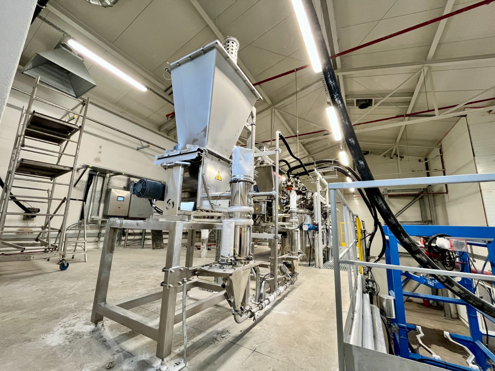
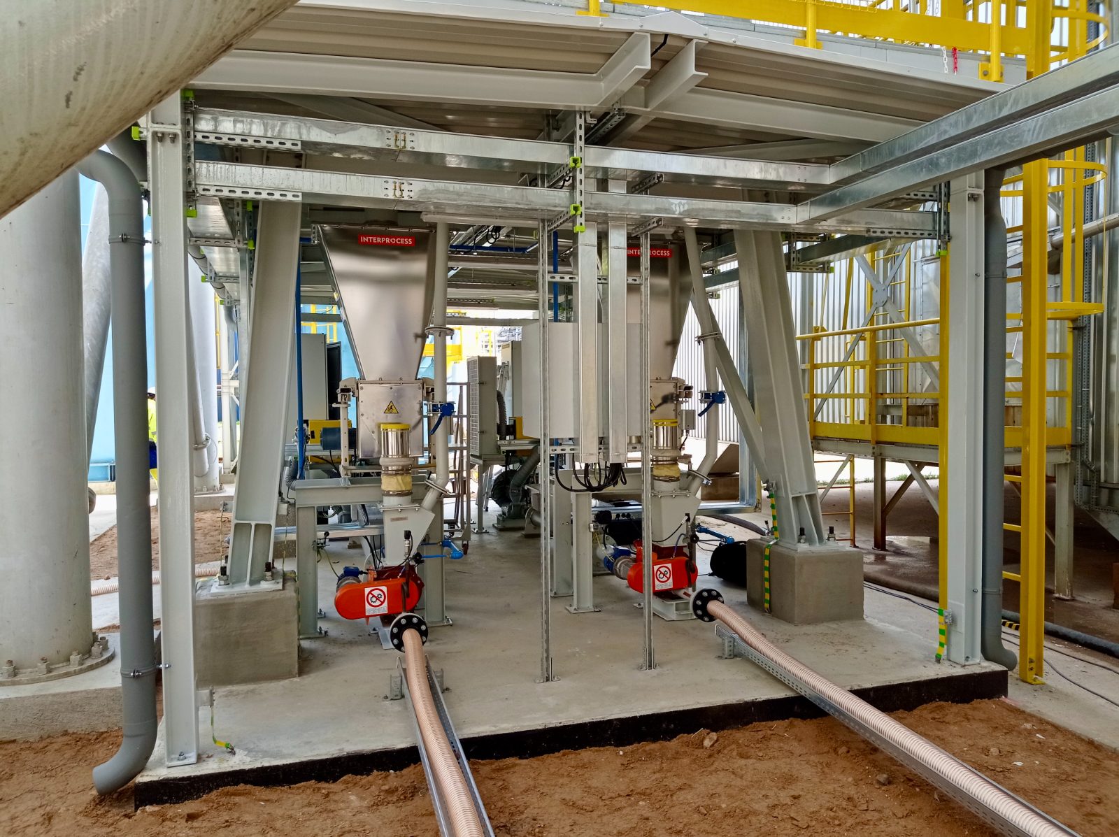
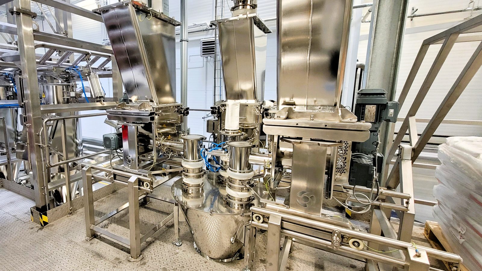
DSL G installations · click to enlarge
Choosing the feeding element
Spiral or full-flight screw?
The choice between screw and spiral decides how even the stream is and how stable the control loop stays. We match the type of element to the properties of the material, not to the size of the feeder.
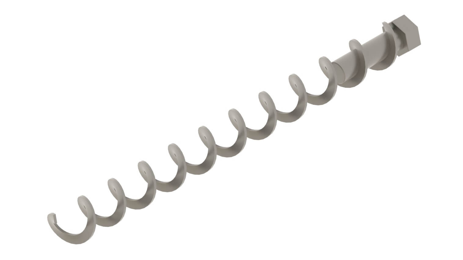
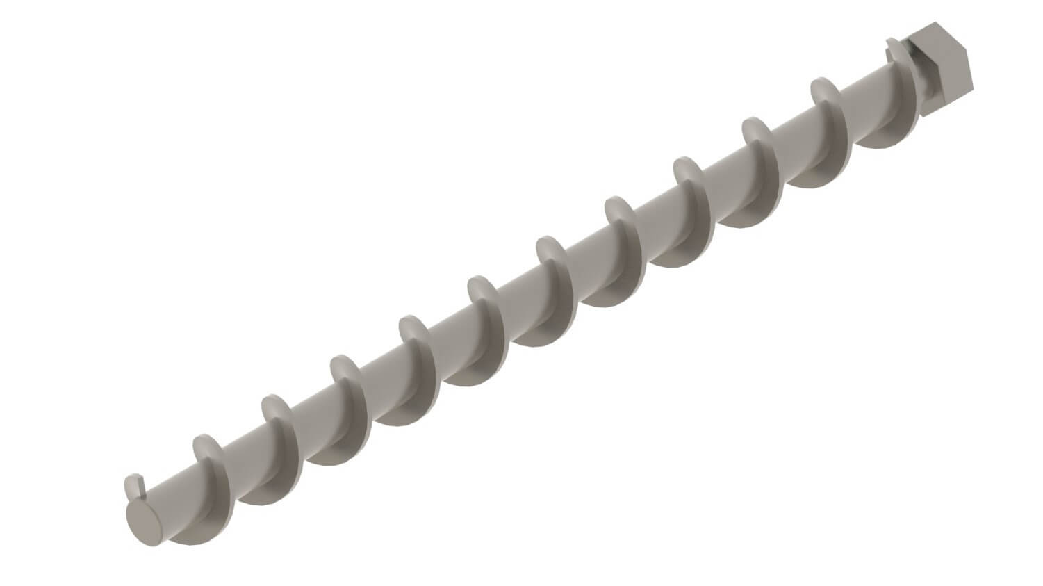
Not sure which element to choose? We run feeding trials on the customer’s own material: the choice of screw or spiral is confirmed by measurement, not by catalogue data alone.
Arrange a material trialBuild variants
EHEDG hygienic version and ATEX build
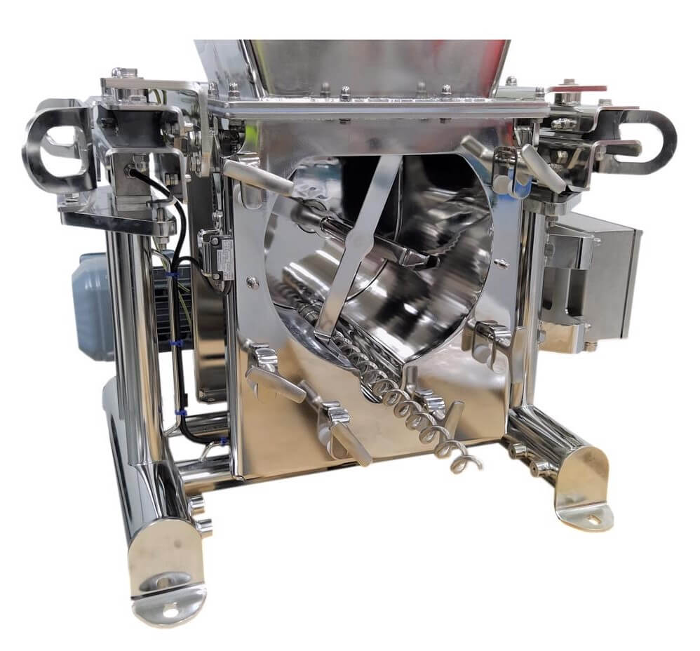
Hygienic version to EHEDG
The standard build already meets the requirements of the food industry: every material in contact with the product is either FDA approved or stainless steel.
For demanding applications we offer a build to EHEDG guidelines: chamber and frame designed for easy cleaning, feeding element and agitator removable without tools, 316L steel, interior and welds ground to Ra<0.8 µm, and aseptic motors without fins or a fan.
Lubricants are exclusively NSF H1 grade. Electrical enclosures are optionally to the Rittal HD (Hygienic Design) standard: stainless steel, sloping surfaces, resistant to high-pressure washdown.
Feeders in explosive atmospheres (ATEX)
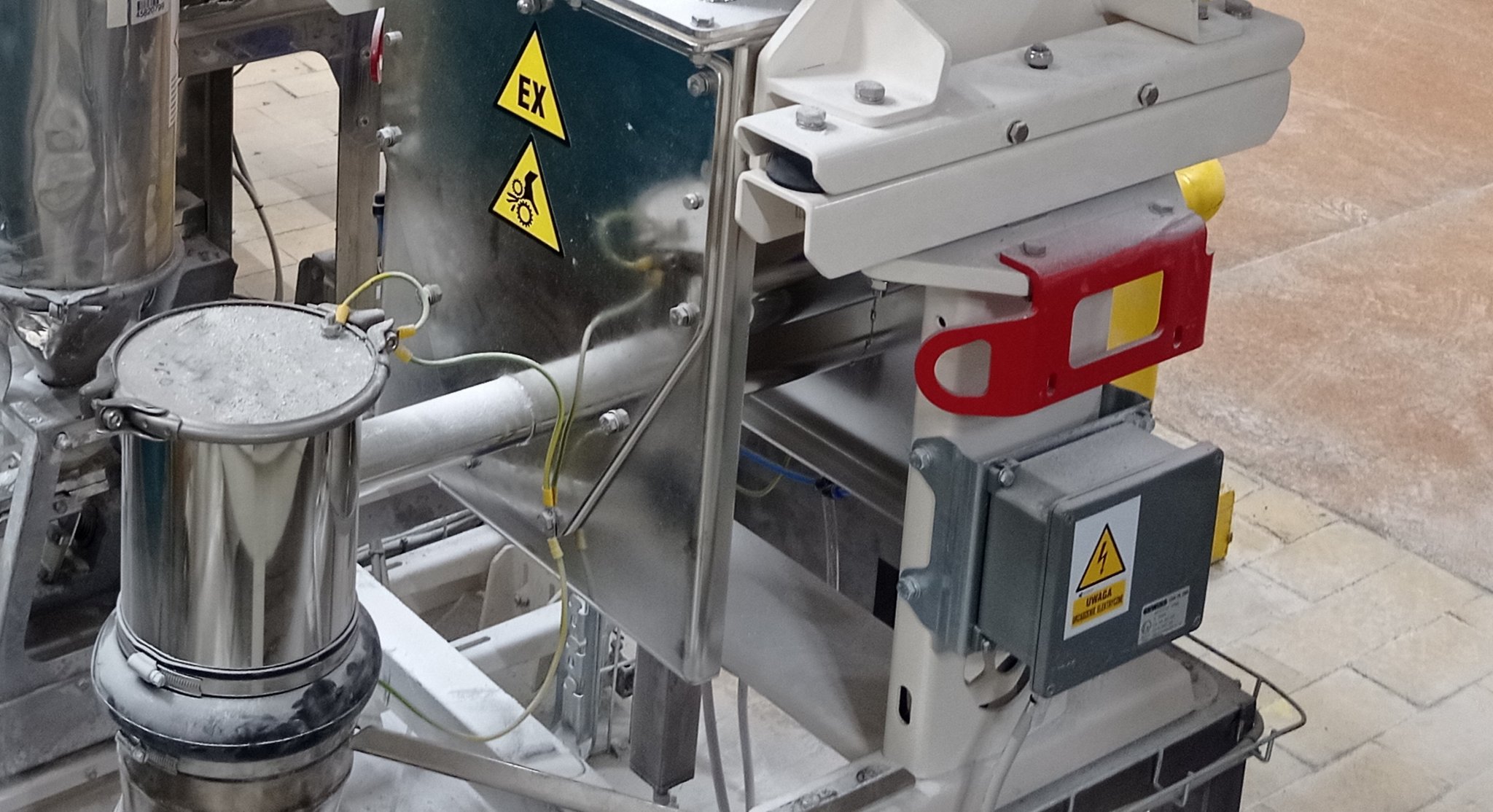
For zones with a risk of dust explosion we supply feeders built in accordance with the ATEX directive: certified electrical components, drives and sensors in the appropriate category, and continuity of equipotential bonding to carry off electrostatic charge.
Gravimetric vs volumetric
Which feeding method should you choose?
A volumetric feeder delivers material at a constant screw speed and assumes a constant bulk density; with no feedback loop, every change in the material’s properties turns into a feeding error, typically ±1–5%. A gravimetric feeder measures the loss in weight and corrects speed in a closed loop, holding the error below ±0.5% whatever the raw material. The difference matters with multi-ingredient recipes, expensive raw materials and quality audits.
| Parameter | Gravimetric loss-in-weight | Volumetric |
|---|---|---|
| Measuring principle | Continuous measurement of loss in weight | Constant volume per unit of time |
| Accuracy (continuous feeding) | <±0.5% of setpoint | ±1–5% of setpoint after linearisation of the range |
| Accuracy (batch feeding) | ±0.1–0.5% (depending on load cell range and batch size) | No direct control of batch mass |
| Compensation for density changes | ✓ Automatic, closed loop | ✗ None, requires calibration |
| Real-time control | ✓ PID controller | ✗ Open-loop control |
| Flow records | ✓ Actual mass flow is logged | ✗ Only rotational speed is monitored |
| GMP / HACCP compliance | ✓ Full validation and batch traceability | Limited |
| Capital cost | Higher (weighing system plus controller) | Lower, simpler construction |
| When to choose it | Multi-ingredient recipes, expensive raw materials, quality audits | Homogeneous materials of constant bulk density |
DSL G feeders can also run in volumetric mode. Simpler applications are covered by our volumetric screw feeders.
Operating modes
Continuous and batch feeding
Every DSL G works in both modes; switching happens in the controller. The choice depends on the nature of the production, the flexibility of the recipes and the output required.
Continuous feeding (continuous)
Material is delivered without interruption at a controlled mass flow. The controller compares the measured loss in weight with the setpoint and corrects screw speed continuously.
- a steady, precisely controlled stream of material
- feeding continuous mixers, extruders and reactors
- automatic changeover to volumetric mode while the hopper refills
- integration of several feeders in a master/slave system
- a marked reduction in material losses
Batch feeding (batching)
A set mass of material is metered out. Once the batch is complete the feeder stops and waits for the next cycle; typical accuracy is ±0.1–0.5% for batches above 1 kg.
- precise metering of a set mass with a final check
- full traceability of every batch
- handling of multi-ingredient recipes
- simplified validation in pharmaceutical production (GMP)
- a proven solution where the product changes often
Refilling the hopper without interrupting feeding
The weighed assembly is joined to the filling system and the discharge tube by flexible sleeves, so external forces do not affect the measurement. When the level in the hopper falls below the minimum, the controller starts the refill and the feeder changes over to volumetric mode at the last recorded speed. Once the hopper is full it returns to gravimetric control.
Batch feeding
Recipe-based feeding
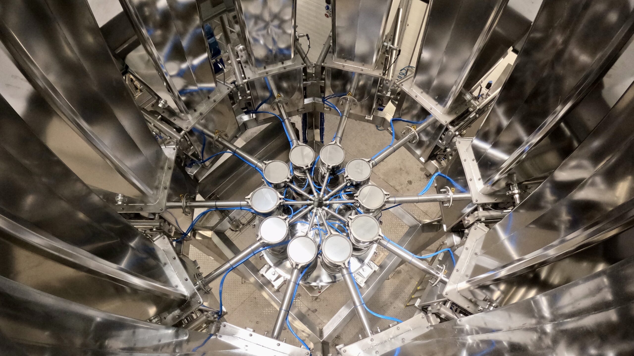
We build screw feeders into multi-ingredient batching stations, in which each unit delivers a separate raw material. A master controller derives the batch size or the flow rate from the recipe, working in batch mode or continuous mode.
The weighing arrangement is decided by the number of ingredients, the cycle time and the accuracy required:
Gain-in-weight
Weighing into an external scale
The least expensive batch arrangement: ingredients arrive one after another in a common hopper scale. Where demands are high, intermediate scales or a travelling scale positioned under each feeder in turn are used. Homogenisation takes place in the mixer.
Loss-in-weight
Feeding directly from the scale
Each feeder has its own scale, so the ingredients are delivered in parallel. This shortens the cycle and pre-homogenises the blend during feeding itself. In continuous mode it allows a batch mixer to be replaced by a much smaller in-line mixer.
Feeding accuracy
What disturbs the weight measurement, and how we compensate
The accuracy of a loss-in-weight feeder depends on the material and on what surrounds the scale, not on the electronics alone. The most common sources of error and the way they are compensated in the DSL G:
Vibration and shock
Vibration from neighbouring machines and from the building structure is damped mechanically in the feeder frame, and the load cell signal is filtered digitally in the controller.
Pressure differences
Negative or positive pressure in the discharge tube, the operation of a mixer or nitrogen blanketing all distort the measurement. We apply pressure compensation at the inlet and outlet together with flexible decoupling sleeves.
Bridging in the hopper
Cohesive materials hang up above the screw. The answer is agitators, a suitable wall angle in the hopper and, for the most difficult powders, a hopper with a loosening system.
Varying bulk density
The density of the raw material changes with the batch, the moisture content and how full the hopper is. The gravimetric controller corrects the speed continuously, so the set mass flow stays constant.
Blockages in the feeding tube
Caking or fibrous products block the feeding element. We select screws of variable pitch, or a spiral with no centre shaft, which loosens the material by itself.
Short-term accuracy
At very low rates what counts is how even the stream is from second to second. Multi-start screws, higher speeds at a smaller cross-section and special discharge tube ends all improve it.
Proportional feeding
Multi-ingredient feeding systems
In continuous proportional feeding, several loss-in-weight feeders deliver ingredients simultaneously onto a common conveyor or straight into the process. Each measures the loss in weight of its own hopper, so the flow of every ingredient is known and controlled independently. One feeder works as the master, the rest as slaves, holding a fixed mass ratio to the main ingredient.
A change in the master feeder’s rate changes the rates of all the slaves proportionally, so the recipe ratios hold whatever the line output, and hoppers refill without interrupting feeding. InterProcess supplies complete stations: feeder selection, weighing controllers with industrial communication, and recipe automation.
Industries and applications
Applications in key industries

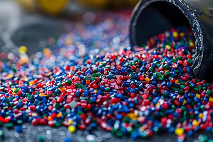
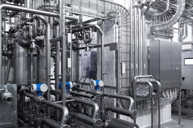
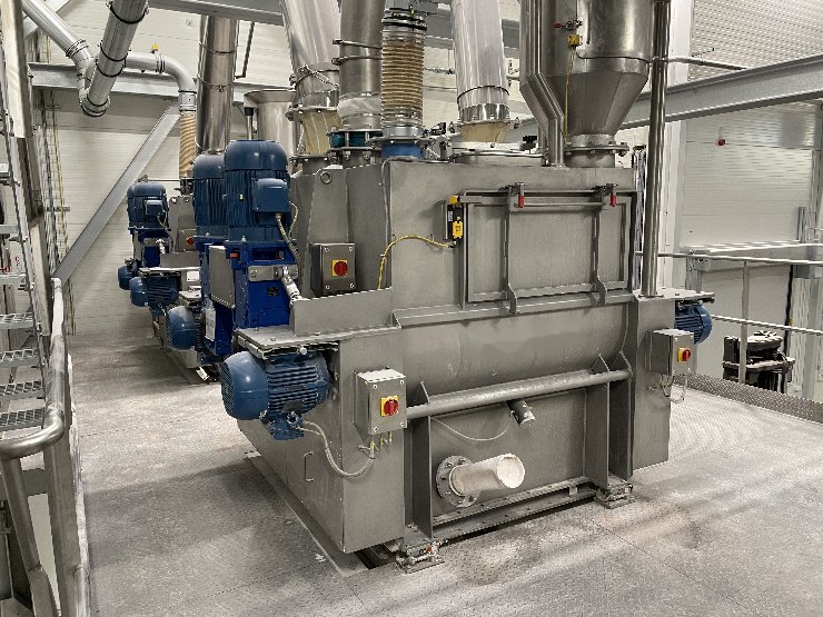

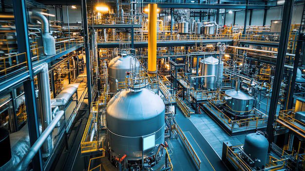
FAQ
Frequently asked questions
Why InterProcess
Why choose our solutions?
In-house manufacture
We design and build DSL G feeders in our own works.
Feeding trials
We will test your material on a real feeder before you buy.
Complete delivery
From design and material trials through to commissioning and service.
Experience across many industries
Food, chemicals, pharmaceuticals, plastics and power.
Safety and hygiene
Systems compliant with ATEX, HACCP, GMP and EHEDG.
Technical support and service
A fast response, 24/7 if required.